
Little risk of CO₂ migration
Before CO2 is injected into a reservoir, its ability to keep the gas will be carefully examined. There is broad agreement in the research community that the risk of migration from well-known geological structures, is little. However, it’s important to control the factors that impact the storage ability.
Secure storage
THERE IS A HIGH DEGREE of certainty that the first structures selected for storage, are impermeable. However, for CCS to be an effective way of curbing climate change, a large number of storage locations are needed. So with time, it will be necessary to store CO2 in less optimal formations.
“The risk of storing CO2 will still be very small – and dramatically smaller than not doing so. After all, a major part of the CO2 we release to the atmosphere ends up in the oceans. However, we want to be as certain as we possibly can, and achieve a better understanding of what could happen in the ocean if CO2 should seep out,” says project coordinator Guttorm Alendal at the University of Bergen.
The MayMoDo project
The BayMoDe project has contributed to developing methodologies for understanding such events better. The project has been conducted in close cooperation with a major EU project, STEMM-CCS, and builds on a previous project, ECO2.
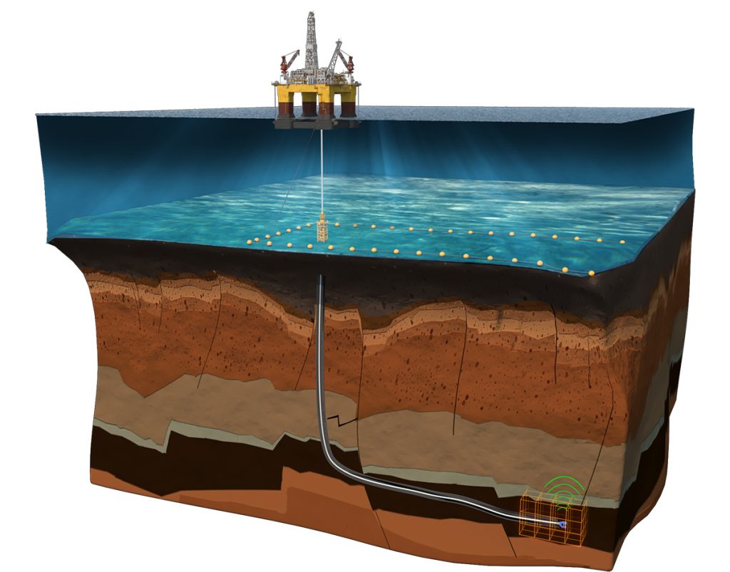
“In BayMoDe we are not investigating the risks of migration of the stored CO2, but only scenarios where CO2 travels through the seabed into the water column,” says Alendal. “In such a scenario, CO2 will either percolate through the seabed in the form of bubbles or already be dissolved in the sea water within the seafloor sediments. Through several projects, we have developed mathematical tools that simulate how the CO2 will be transported.”
This knowledge is necessary to design environmental monitoring programs and to assess risks associated with large-scale offshore storage of CO2.
Limited consequences of emissions
In a hypothetical case where CO2 escapes in pure form in the North Sea, it will be in the form of gas bubbles through the seabed. The bubbles will ascend through the water column and rapidly dissolve in the water, and be transported by the local water bodies. Increased CO2 content causes acidification, with possible environmental consequences. However, this impact will rapidly subside as we move away from the source. Because of the shifting current conditions, e.g. tide and local small-scale variability, the signal of the seep will soon be hidden within the natural variability.
“Our estimates show that the consequences of these types of seeps will be limited. In the rare instance that this should occur, the result could be acidification of an area similar to a football field in extension. Still, some areas are more vulnerable than others, for example breeding grounds or coral reefs,” says Alendal.
Measurement programme
A monitoring programme gives a better overview over the factors that impact the marine environment. As an example, the ongoing net transport of CO2 from the atmosphere causing acidification of the biologically most productive surface layer, is an often under-communicated consequence of increased atmospheric CO2 concentration.
In fact, an effective programme for measurement dovetails with UN’s sustainability goals, especially SDG14 life under water, through co- operation with other marine monitoring programs. Often, the SDG13 climate measures is used as the only argument for implementing large-scale storage of CO2.
Because CO2 exists naturally in the ocean, and the concentration fluctuates according to time and space, it’s a challenge to separate the signals of releases from the natural variability in CO2 concentration. BayMoDe has contri buted to the development of methods to design measurement programmes that quantify and reduce the probability of false alarms.
Mathematical models
The methods are based on simulations of transport in the water masses using mathematical models, so-called ocean circulation models. These models are being used in many contexts, for instance it has been used for climatological simulations in the North Sea from the 70’s and onward, and they are used by weather services to produce ocean forecasts. A hypothetical source is added, and transport and dilution of the CO2 signal are simulated and these prediction are subsequently used in simplified and statistical models.
“We have focused on identifying methods for modelling a probable footprint of a migration, by combining measurement statistics, mathematical modelling and Bayesian probability estimations,” says Alendal.
The results of BayMoDe will be developed further in new projects. For instance, a web-based software is being developed in a recently started ACT-financed project, ACTOM.
Facts about the project
Bayesian Monitoring Design (BayMoDe)
Project owner: University of Bergen
Project period: 2016–2020
Total budget: 9.3 MNOK
Support from CLIMIT: 6.6 MNOK
Partners: NORCE, Plymouth Marine Laboratory and Heriot-Watt University
Solutions for future CO₂ storage
In the SWAP-project, Equinor has collected strategic subsurface data in order to explore the possibilities of storing large amounts of CO2 in a saline aquifer east of the Troll field.
SWAP
SWAP IS PART OF EQUINOR’s Scale-up of CO2 Storage project, and is closely connected to the company’s hydrogen strategy. In the production of hydrogen from natural gas, large amounts of CO2 are formed, which Equinor is planning to store on the Norwegian Continental Shelf. The need for storage sites will increase as carbon capture becomes a widely used technology for reducing emissions from industry in Norway and Europe.
“Our intention was to explore the potential for large-scale CO2 storage at the Horda platform, in the Troll area, and is closely connected to the potential future phases of the Northern Lights project,” says project leader Rune Thorsen in Equinor.
Better understanding of pressure
Northern Lights encompasses transport and permanent storage of CO2 in a geological formation under the North Sea, and is a constituent part of the Norwegian full-scale CCS project. In an early phase, the Northern Lights project considered storing CO2 at Smeaheia, an area east of the Troll oil and gas field. After the feasibility study, however, uncertainties arose regarding some of the assumptions undergirding the project.
Studies showed that there was a possibility that the reservoirs of the Smeaheia area could be linked with the reservoir sandstones at Troll. If there was a large degree of pressure communication between the areas, it could impact the storage capacity on Smeaheia. Since Troll will produce gas until 2054, the pressure at Smeaheia could also fall as the pressure falls at Troll in the years to come.
Usually, CO2 is injected into a reservoir in a liquid state. If the pressure at Smeaheia falls significantly, the CO2 could expand from liquid to gas, which occupies more space in the reservoir. Therefore, it might not be possible to store as much CO2 at Smeaheia as the plans predicted. This was one reason that Northern Lights instead opted for a storage location in the Aurora area, south of Troll Vest.
“However, in the Scale-up of CO2 Storage-project, we decided to continue working internally with the area that was abandoned in 2018,” says Thorsen. “We hadn’t lost faith in the Smeaheia area as a future storage location, but we needed more time to find answers to the uncertainties that had been identified. The time frame for the full-scale CCS project was so tight that we had to mature other alternatives in order to reach a positive investment decision in 2020.”
More well data
The first plans for the SWAP project appeared during the summer of 2018. Equinor had been awarded an exploration licence in the south of the Smeaheia area (PL921) during the spring of 2018. The goal was to explore for hydrocarbons in the Gladsheim structure. This structure is situated approx. 20 km south of the area that had been studied in the first phases of Northern Lights, and exploration drilling was scheduled to start during the fall of 2019.
The planned exploration drilling was identified as a rare opportunity for collecting additional strategic data, which could reduce the geological uncertainties identified by Northern Lights – so that the future road to CO2 storage on Smeaheia might be both shorter and cheaper.
Towards the spring of 2019, the SWAP project assumed shape. SWAP – the Strategic Well Acquisition Project – became a project for gathering important subsurface data. Although these data would otherwise not have been acquired by the exploration licence, they are considered important pieces of information in order to create an understanding of the storage potential in the area around Troll.
A large part of the extra collection consisted of data from the cap rock. The data confirmed that the cap rock will remain impermeable if CO2 should be injected into the reservoir. Core samples were taken and rock- mechanical tests executed in order to determine the quality and strength of the cap rock. The researchers also measured the porosity, permeability and fracture pressure of the rock in a thick slate, the Draupne formation. Usually, these types of samples of the cap rock are not taken in an exploration well.
Pressure measurement
Below the cap rock, Smeaheia consists of several geological formations that potentially can be used for storage. As a part of the SWAP project, a set of pressure measurements were conducted in the different reservoirs, in order to measure the degree of communication with the Troll field.
“The measurements showed that the pressure was reduced in the well area,” says Thorsen. “Then we knew that the sands we had hit, were connected with the Troll sands. This means that the reservoir is vast, and that it’s possible to inject large amounts of CO2 without a significant increase of the pressure of the reservoir.”
“We have also taken small core samples of the different levels of the reservoirs, so-called sidewall cores (SWC), on which we will conduct different tests in the laboratory,” says Thorsen.
Now the researchers are working on updating models and increasing the understanding of the reservoir. Will it be possible to use this area for injection– for example in a future scale-up of the Northern Lights project?
“There is great reason for optimism,” says Thorsen. “The data suggest that the sealing is solid. The reservoir has thick rocks over a large extension. This means that the area probably can receive large amounts of CO2.”
The results of the project can also have positive repercussions for Northern Lights.
“At a future scale-up of Northern Lights, the area we are exploring can probably be used as a storage site. This means that we can potentially use the infrastructure that will be built in the first phases of the project. This way, we can achieve large cost reductions,” says Thorsen.
About the project
Strategic Well Acquisition Project (SWAP)
Project owner: Equinor
Project period: 2019–2020
Total budget: 26.7 MNOK
CLIMIT-support: 17.3 MNOK
Partners: Petoro, DNO and Lundin
Unprecedented interest for latest ACT call
ACT’s 3rd funding call for CCUS projects that was launched in June, has received a record breaking 91 pre-proposals.

The unprecedented interest
“The ACT consortium is delighted to note the unprecedented interest in the call and that all researchers and innovators from all ACT countries/regions have joined in submitting pre-proposals. This interest is testimony to the uniqueness and added value of this international funding instrument for CCUS research and innovation, says ACT coordinator Ragnhild Rønneberg.
ACT is an international initiative to establish CO2 capture, utilisation and storage (CCUS) as a tool to combat global warming.
The ACT3 applicants come from all 15 participating countries/regions, with potential cooperation partners from countries outside ACT.
€30-40 million
The total budget available for successful projects answering to this call is in the range of €30-40 million. Indicative funding requests from the 91 pre-proposals amounts to approximately €160 million.
Based on the high quality of proposals submitted and funded in earlier ACT calls, the ACT consortium expects ACT3 to be another highly competitive call.
The pre-proposals will now be evaluated for their eligibility according to procedures and national specifications/requirements described in the call text.
Eligible pre-proposals will be informed by 11 December whether they will be in ivited to submit full proposals for the second stage of the ACT3 call evaluation.
The due date
The due date for submission of full proposals is 15 March 2021 at 13:00 CET.
About ACT
Click here for more detail on the ERANET ACT.
ACT is an international initiative to establish CO2 capture, utilisation and storage (CCUS) as a tool to combat global warming.
ACT means Accelerating CCS Technologies, and the ambition of the 14 partners is to fund research and innovation projects that can lead to safe and cost-effective technology.
The ACT community has welcomed new members since its first calls. The following countries and regions participate in the ACT3 Call: the Canadian province of Alberta, Europe’s Nordic Countries via Nordic Energy Research, Denmark, France, Germany, Greece, The Netherlands, Norway, Romania, Switzerland, Turkey, the United Kingdom, and the USA.
New fuels for carbon free power production
The BIGH2 project develops advanced combustion technology that utilizes mixtures of hydrogen and ammonia as carbon-free fuel in industrial gas turbines.
Engines that can use carbonfree fuels before 2030
GAS TURBINE MANUFACTURERS aim to deliver engines that can use carbonfree fuels before 2030. The gas turbines must have the same level of performance as today’s state-of-the-art equipment, powered by natural gas, and meet current requirements regarding emissions of nitrogen oxides and other pollutants.
The project explores key challenges related to the use hydrogen and ammonia as gas turbine fuels: to ensure a stable flame in the combustion chamber and avoid emissions of
nitrogen oxides that exceed regulatory standards. Hydrogen represents, in many respects, an optimal fuel because it burns easily in a very stable fashion and, if certain combustion conditions are satisfied, also very cleanly as its only combustion product is water vapour.
However, hydrogen also poses important logistical challenges because the gas is highly explosive and characterized by very low energy density. Therefore, it’s problematic to store hydrogen safely in very large quantities.
A convenient hydrogen and energy carrier
The BIGH2 project investigates the possibility of using ammonia (NH3) as a hydrogen carrier because ammonia is considerably easier to handle than hydrogen.
While hydrogen is a relatively new fuel in the transportation and power generation sectors, still lacking well-established logistics and infrastructure, ammonia is already
produced, transported and stored in large quantities for the manufacture of fertilizers, for example.
“Ammonia is a very well-known chemical, and we draw on comprehensive, accumulated experience from all links of the value chain. An extensive distribution network is already in place, and we have effective systems and safety mechanisms for handling the chemical,” says project director Andrea Gruber at SINTEF.
So, how could ammonia be used as an energy carrier in the production of power with large gas turbines?
Upgrading ammonia
The challenge with ammonia is that it’s a rather poor fuel, especially for gas turbines, characterized by weak ignition and combustion properties and by a rather obnoxious tendency to form atmospheric pollutants (nitrogen oxides, NOx) in the exhaust. Hence,
BIGH2 aims to find out if blending ammonia and hydrogen can result in a better gas turbine fuel than neat (pure) ammonia. A fuel mixture consisting of hydrogen, nitrogen and ammonia can be readily obtained by cracking the ammonia molecule into hydrogen and nitrogen by heating the chemical in a catalyst. Vast amounts of waste heat are often available in gas turbines as bi-product of the combustion process.
“Before sending the ammonia into the gas turbine, the chemical compound can be cracked, completely or partially, by using surplus heat – and using the resulting hydrogen, which is a highly reactive element, to upgrade the fuel mixture,” says Gruber.
“In this project, we try to understand how different blends of ammonia, hydrogen and nitrogen behave in the combustion chamber, compared to natural gas.”
It’s important to find the “sweet spot” and limit the cracking of ammonia to ensure a stable and clean combustion. This is also important because the cracking process itself uses surplus heat from the gas turbine, and this heat has alternative utility value for steam turbine cycles or district heating. Therefore, the intention of the project is to identify the optimal mixture of hydrogen, nitrogen and ammonia that requires as little cracking of ammonia as possible.
NOx reduction
Another important challenge presented by the combustion of ammoniacontaining fuels, is that toxic nitrogen oxides (NOx) are a by-product of the process.
“So our focus is, beside flame stability, also on minimizing the formation of NOx in the combustion chamber,” says Gruber. “We are trying to identify the operating conditions that produce the lowest level of NOx, for instance by organizing the chemical reaction process in different stages within the combustion chamber.
But, if this strategy fails, we are also considering using some of the ammonia as a reduction agent for NOx abatement in the exhaust gas.”
The researchers investigate the challenges from different angles.
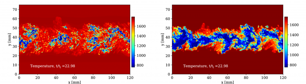
“At SINTEF, we are trying to deepen our knowledge of the basic combustion process. We have modelled the flames of hydrogen and ammonia, in order to better understand the effect of these new fuel mixtures. This has required a comprehensive and coordinated effort together with our research partners, NTNU in Trondheim and Sandia National Laboratories in California,” says Gruber.
Laboratory experiments have also been conducted utilizing SINTEF’s pressurized combustion rig (HIPROX) at Gløshaugen, where a downscaled version of a gas turbine burner is used to evaluate flame stability and NOx reduction strategies.
Close cooperation
“We are using a very complex and advanced Siemens gas turbine burner, where the combustion process is compartmentalized into three stages.
We are conducting tests with different compositions of the fuel in the different
stages. For instance, we can inject undiluted ammonia in one stage and add cracked ammonia in the other two, trying to find the optimal operation point.”
At the same time, NTNU conducts experiments on simpler flames using less complicated burners compared to the Siemens’ design and these experiments have spawned valuable fundamental knowledge on how these new fuel blends behave compared to natural gas.
“Ours is a fine group of partners. The combination of different research groups at SINTEF and NTNU, and the industrial locomotives Siemens and Equinor – both having concrete plans to develop hydrogen and ammonia as energy carriers – has been of immense value to the project. Sandia National Laboratories, the US Department of Energy leading research lab in the field of energy technologies, is involved in the project as an external associated partner. Together we are maturing a technology that now needs a small push to become a reality,” says Gruber
DigiMon webinar on digital monitoring of CO₂ storage
The ACT2 DigiMon project invites to an open webinar to present results from the ongoing research co-funded by CLIMIT.
Webinar about CO2 monitoring
The overall objective of the ACT CCS DigiMon project is to “accelerate the implementation of CCS by developing and demonstrating an affordable, flexible, societally embedded and smart Digital Monitoring early-warning system”, for monitoring any CO2 storage reservoir and subsurface barrier system.
Cost-effective solutions in maritime transport
The CO2LOS project aims to reduce the costs of transporting CO2 on ships.
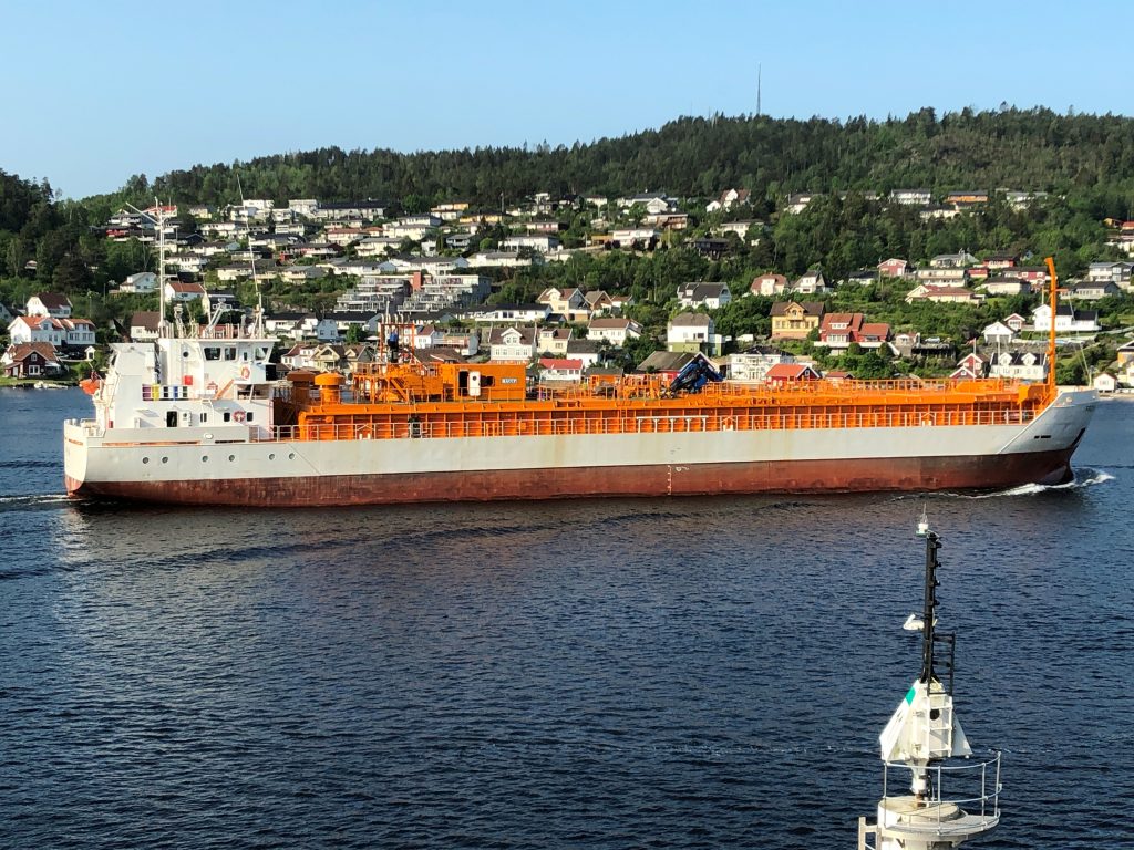
A mature technology
“TODAY’S CONCEPTS FOR CO2 CAPTURE are based on the assumption that much of the transport will occur through pipelines to the storage location,” says project director Martin Hay at Brevik Engineering.
“There has been less focus on solutions for ship transport, partly because this area has been considered a mature technology, and partly because the costs have been seen as low in comparison with the total costs for CCS technology. However, as the costs of capture and storage are reduced, transport costs become relatively higher.”
Northern Lights – the infrastructure part of the planned Norwegian fullscale CCS project – has chosen ship transport for the project’s first phase, based on the current practice for CO2 transport. This is technology equivalent to what is used for small scale transport for the food and beverage industry.
Different solutions for ship
CO2LOS sees beyond the first phase of Northern Lights. The project evaluates different transport solutions from an onshore export terminal to an onshore import terminal, for example a process plant on the western coast of Norway, where the gas is compressed and pumped through a pipeline and out to the storage location under the sea.
The project is also considering two options for offshore unloading. Option one is to load CO2 to a “storage tank” at sea, a Floating, Storage and Injection Unit (FSI), which injects the gas into the geological storage formation.
The other option is to do the injection directly from the shuttle tanker. This solution requires additional equipment onboard the ships.
The selection of method is determined mainly by whether the storage formation requires a continuous injection of CO2 or if batch-wise injection is possible.
“The advantage of offshore unloading is that there is no need for an onshore installation and an expensive pipeline from land,” says Hay.
Right pressure
CO2 requires low temperature and high pressure to remain in a liquid form. The Norwegian full-scale project has decided to utilize the same pressure and temperature (approx. 15 bar/-28°C) that is currently used on ships transporting CO2 in smaller scale for industrial purposes.
The gas pressure defines the maximum size of the tanks onboard ships. If pressure and temperature is reduced, larger tanks and, consequently, larger ships can be built.
Larger ships mean reduced transportation costs per tonne of CO2, since the
CO2 volumes for transport and the distances increase.
However, use of bigger ships presents a challenge. This solution requires larger intermediate capacity ofthe onshore facility. And the CO2 must be kept liquid for a longer period of time.
“We have to strike a balance. If we only consider ship transport, bigger ships are cheaper,” says Hay. “But it’s not straight forward. We have to consider the entire transport chain.”
Different concepts
CO2LOS is evaluating four concepts for ships.
One possibility is to equip existing dry cargo ships with new CO2 tanks. This is the cheapest solution. The project also considers barges for the water ways in Europe, which can bring CO2 from industrial plants in the lower parts of the Rhine.
The second concept entails building a new ship, which will transport the gas at low pressure (approx. 7 barg).
The third concept is an autonomous ship that can give significant cost reductions.
The fourth concept consists of design of large ships for transport over large distances.
“All work packages are conceptual,» says Hay. «And we hope to be able to continue this work and create concrete technical solutions.
Facts
Project owner: Brevik Engineering AS
Project period: 2019–2020
Total budget: 14.5 MNOK
Support from CLIMIT: 6.25 MNOK
Partners: SINTEF, Equinor, Total, Gassco, Air Liquide and Sogestran
Cleaner hydrogen production
The calcium-copper looping technology is promising.The aim is to produce hydrogen and capture CO2 in one step. And do it cost-efficiently.
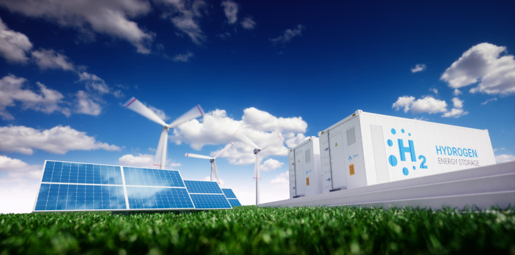 2 HYDROGEN ENERGY STORAGE" skrevet på dem. Illustrasjon." class="wp-image-1536"/>
A long tradition
IFE (INSTITUTE FOR ENERGY Technology) at Kjeller, Norway, draws on a long tradition of collaboration with industrial companies.
“Our core business is to help industries to move to the green shift with specific technologies, and we tailor solutions from there”, says Suni Aranda, head of IFE’s Department for Environmental Industrial Processes.
IFE possesses a comprehensive pool of knowledge in hydrogen, CO2 capture and utilization, as well as process intensification – how to design new processes and make existing processes more efficient.
A well-travelled idea
“We have a very strong belief that working with industry from the concept stage, is key for success”, says Aranda. “It’s important that they are involved. Because we don’t have ready-made solutions in our pockets. We seek to address the practical needs of operational environments.”
The 6Cs project – CO2 Capture by Combined Calcium-Copper Cycles – paves the way for hydrogen production with integrated CO2 capture, and followed this pragmatic approach.
The 6C project was ideated as a spin-off project with origin from a European framework, and it was carried out together with international research and industrial partners.
“I think the 6C project is a successful example of how knowledge travelled back and forth between Norway and Europe, between different research communities, and between researchers and industry players”, says Aranda.
Well calcium-copper?
In conventional hydrogen production, hydrogen is produced in several reactors, where CO2 capture is not integrated and requires considerable energy and dedicated quipment. The calcium-copper looping technology proposes to integrate the entire process into one reactor with sequential steps, alternating gas flows and process conditions.
The 6Cs project also aimed at developing innovative materials for this process. Materials with combined functions reach even further reduction of energy demands and quipment costs. That’s why it’s called process intensification.
The system starts with natural gas,mostly methane, injected into the reactor.
To capture the CO2, the researchers use calcium oxide as a sorbent. Under specific conditions, calcium oxide captures CO2, and becomes calcium carbonate. The next step is to release the CO2 from the calcium carbonate, in a concentrated form, ready for its utilization or storage. The sorbent is regenerated back to calcium oxide, and made available for a new cycle where it can capture the CO2 again.
The regeneration of the sorbent takes place at a high temperature. How heat is transferred at this high temperature, is crucial in terms of how viable this process will be. In the calcium-copper looping cycle, the heat is generated and transferred via the copper in-situ, by the exothermic reduction of copper in contact with reducing gases (H2 and CO). The heat transfer comes from solid-gas chemistry. There is no additional external source of heat for the regeneration of the sorbent.
“Copper is reduced while calcium carbonate is decomposed, and the reduction of copper is exothermic. It means that it emits heat that is necessary for the calcium carbonate to release the concentrated CO2, and form calcium oxide for a new cycle,” explains Luca Di Felice, project director.
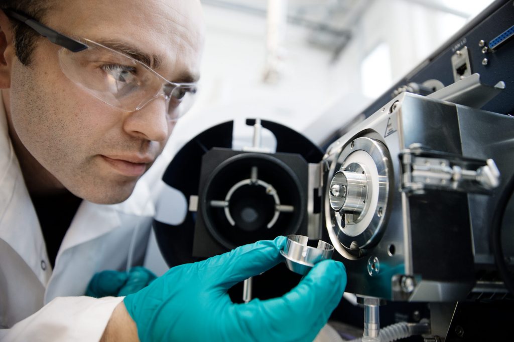
A combined material
The crux of the process design is to merge functions in the same material. Calcium and copper are combined into composite particles. The combined material – which contains both the sorbent and the heat carrier – must have adequate chemical, physical and techanical properties. It has to go through the chemical cycles, withstand high temperatures and changes of temperatures, and tackle possible impurities in the gas. The focus of the research revolved around the stability of different materials.
“For example, in specific circumstances, spots within the material can melt. This is one of the challenges with copper. You have to spread it nicely, so it’s stable and still reactive over cycles. This has been a scientific challenge,” says Di Felice.
At the completion of the 6Cs project, the calcium-copper looping technology is way more than a concept. The research team has carried out comprehensive simulation and laboratory testing. Now the aim is set for further verification on an industrial-level scale.
Partners are such as Instituto de Carboquímica in Spain, the University of Bergen, the Norwegian Institute for Air Research and the Eindhoven University of Technology in the Netherlands. Industrial partners were Johnson Matthey, the UK developer of sustainable technologies, and a coppermining company, Cobre Las Cruces, in Spain.
A new wave of technology for clean energy conversion
Innovative looping technology may pave the way for industrial applications. Gas switching combustion may be used for power generation or hydrogen production.
No off-shelf technology
THE REASON THAT CARBON CAPTURE technology has not been commercialized as expected, is that they all carry a significant energy penalty. If industrial companies want to capture CO2, they will have to spend more energy. And the costs will soar.
“There is simply no off-shelf technology that companies can buy, without having to burn more fuel and spend more energy to capture CO2 ,” says project director Shahriar Amini at SINTEF. “So today, implementation hinges on incentives and funding from governments.”
Amini heads a project called GaSTech – Demonstration of Gas Switching Technology for Accelerated Scale-up of Pressurized Chemical Looping Applications. The aim of this research effort is to develop cost-effective, affordable CCS-technology.
The point of departure for the project is conventional postcombustion processes. In chemical looping combustion, there are two reactors. In the first reactor, an oxygen carrier material (i.e. a metal oxide), is oxidized by air. The next step, in the second reactor, the oxide is reduced by natural gas.
The solid metal or metal oxide exists in the shape of powders. Hence, the oxygen carrying material – whether in the form of metal or metal oxide– keeps looping between the two reactors. The chemical reaction in the oxidation stage creates a very high temperature in the stream of gas, which can be used in power plants to create electricity.
Limitations of conventional technology
However, there are certain limitations to the conventional process. “If you want to scale up this reactor system in very large units, the circulation of solids is very difficult”, explains Amini.
“You would need to apply very high pressure for higher efficiency–and operating two pressurized units complicates the industrial design and operation.”
Consequently, Amini and his group of researchers have taken this technology one step further. The gas switching combustion process uses one single reactor. Instead of moving the oxygen career materials from one reactor to another, a valve in the reactor inlet switches between injecting natural gas and air into the reactor.
Smaller modules are connected
“Let’s assume that the metal powder oxide in the reactor is iron oxide, FeO,” explains Amini.. “At the inlet of the reactor, a valve is adjusted so that natural gas flows into the reactor. The natural gas will react with the oxygen of the FeO, reducing the oxide to metal (Fe). The outlet gas coming out of this reaction is a pure stream of CO2 with water vapor. After separation of water vapor easily through condensation, a very pure stream of CO2 is created, which then can be compressed and transported for storage.
Then, the valve is set to inject air. The Fe reacts with the oxygen of the air, converting the iron to iron oxide. This is an exothermic reaction that creates a stream of gas with temperatures up to 1000 °C. The air, deprived of its oxygen, now consists mainly of nitrogen that can be led into a thermal power plant to produce electricity.
“It’s about simplicity,” says Amini. “It’s much easier to scale up a concept with one single reactor. And the beauty of this process, is that we don’t necessarily need to build very large units. We can have smaller plants modules connected to each other to work in a cluster.”
One advantage of the technology is that it’s able to produce both power aswell as hydrogen.
Relevant for Norwegian industry
“This technology can be very relevant for Norwegian industry, because in hydrogen production, natural gas is used as a feedstock, and you can separate CO2 with no energy penalty.” Over the last decade, in a number of projects funded by Research Council of Norway, European Commission and ACT*, Amini and his colleagues have tested this reactor extensively. The next step will be to put the technology to work in a pilot. Hopefully, that will be the next project.
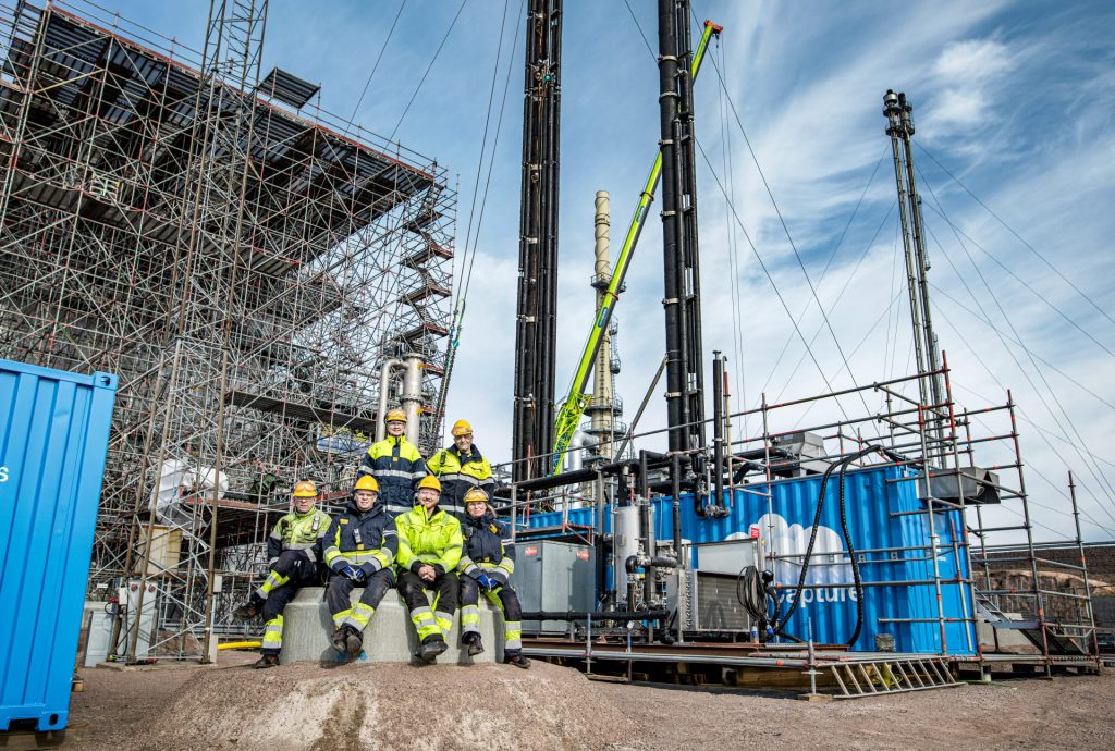
A cleaner refinery
Preem has ambitions of capturing CO2 from the company’s two refineries on Sweden’s west coast. Tests conducted by Aker Solutions will give Preem important operational experience with carbon capture technology.
Sweden’s largest fuel company
PREEM IS SWEDEN’S LARGEST fuel company. The operation encompasses production, distribution as well as trading and product sale. The plants in Lysekil and Gothenburg are amongst the most modern and lowest CO2-emitting refineries in Europe. They have a combined capacity of over 18 million cubic meters of crude oil per year and discharge approx. two million tonnes of CO2 every year.
Test unit
“Preem has a vision of being a leader in the transition towards a sustainable society,” says project director Karin Lundqvist. “And carbon capture will be a necessary measure to reduce emissions of CO2 to the atmosphere. The vision entails building full-scale capture plants at the refineries. This will decrease the discharges significantly.”
After meticulous planning, Preem has now startet testing. Aker Solutions has developed a complete pilot-scale mobile test unit (MTU). Parts of the installation are assembled in containers, and these are fast and simple to mount on different parts of the production plant.
The MTU will be in operation from May to October 2020 at the refinery in Lysekil. The test unit will capture CO2 from the flue gas generated in a production plant. In a downscaled absorption tower – with a diameter of a mere ½ meter – the flue gas flows through an amine solution that absorbs CO2. The amine is then heated in a regenerator tower, and releases the CO2, which can be isolated in pure form at a later stage. In the last step, the amine is recycled and can be re-used in the process.
“In the test phase we investigate how we can optimize the process for the types of flue gases generated at our refineries,” says Lundqvist. “How can we reduce the energy consumption? And how can we ensure that the removed CO2 is as pure as required for long-term storage? We are studying how the amine behaves and how it degrades. We are also working to lower the emissions of amine as much as possible.”
Focus on the Carbon Capture and Storage (CCS) value chain
What are the biggest challenges with the CCS technology? “When it comes to operating the test unit, there are no serious challenges. Rather, it’s important to acquire practical experience with carbon capture at our plant.”
The next step will be to connect the carbon capture facilities at Preem’s refineries to the Northern Lights longterm storage infrastructure, which is a constituent part of the planned Norwegian full-scale CCS project.
“In hooking up to this infrastructure, the challenges are not so much technical as logistical. We are also evaluating the legal challenges of transporting CO2 on ships and over national borders,” says Lundqvist.
The full-scale project encompasses a comprehensive value chain. Firstly, the CO2 will be captured from the production process. Then, the gas will be compressed to liquid form, which occupies less space, and transported to intermediate storage at dedicated loading docks.
“If the planned Northern Lights infrastructure is built, we see this as the natural option for offloading CO2 from our refineries. But our focus on CCS is not solely reliant on this infrastructure,” says Lundqvist.
The Northern Lights route includes transport of CO2 on specialized ships to a hub on the western coast of Norway. From there, the gas will be pumped into a geological structure deep under the sea, where it will be stored permanently.
The Preem CCS prject has the following work packages
- Project management and communication of results
- Demonstration and implementation of CO2 capture
- Process evaluation of full-scale CO2 capture integrated at Preemraff
- CCS value chain analysis, CO2 transport and integration in the Norwegian full-scale CCS project
- Identification of measures to handle legal obstacles for ship transport and storage of CO2 from Preemraff Lysekil for storage on the Norwegian Continental Shelf
- Roadmap for the reduction of CO2 emissions at Preem related to Sweden’s goal of zero net emissions in 2045
The project is supported by Gassnova via CLIMIT-Demo and the Swedish Energy Agency via Industriklivet
Facts about the project
Project: Techno-Economic Feasibility Study of the Implementation of Carbon Capture from Major Emission Sources at Preemraff Lysekil (PREEM CCS)
Project owner: Preem AB
Project period: 2019–2021
Total budget: 28 MNOK
Support from CLIMIT: 9.55 MNOK
Partners: Aker Solutions, SINTEF, Chalmers and Equinor
A driving force for carbon capture and storage
CLIMIT has played a central role in the development of the world’s most dynamic research environments for CCS. Close cooperation with the industry has been a critical success factor.
Is mature and ready for use
IN PARIS IN 2015, the international community agreed that a reinforced commitment is paramount if climate change is to be stopped. The goal set by the signatories, is to limit the increase in temperature to 2°C.
According to the Intergovernmental Panel on Climate Change (IPCC) and the International Energy Agency (IEA), this goal will be near impossible to reach without capturing CO2 from large sources of emissions and storing it deep underground. There is also broad agreement among researchers, industrial players and decision makers
that CCS technology now is mature and ready for use.
Continuity of focus
It has required long-term, goaloriented effort to devise practical solutions for all parts of the value chain.
“CLIMIT has been a driving force in the development of CCS technology. Our commitment has spawned knowledge and solutions that benefit the international community,” says Arvid Nøttvedt, Chairman of the CLIMIT Board of Directors.
“While interest in CCS technology has recovered in Europe, after a period of decline, CLIMIT has been a stable contributer to research in this field. Norway is one of the few countries that has kept a continuous focus on CCS research and development.”
Since the establishment in 2005 and up to 2019, CLIMIT has financially supported almost 500 research projects with more than NOK 2 billion. The research institutions that have
received funds, represent a diverse set of competencies and approaches. Projects have been selected on the basis of a comprehensive evaluation of which parts of the innovation chain that needs funding most.
“It’s the responsibility of CLIMIT’s management and Board of Directors to ensure a balanced portfolio, so we can achieve the overarching goals defined in our program. Hence, CLIMIT has a strategic role,” says Nøttvedt.
In addition to financial support, CLIMIT sees competence sharing as a key goal. Projects receiving funds are encouraged to communicate results to a wide range of stakeholders. Moreover, CLIMIT organizes a major conference biannually, gathering Norwegian and international expertise in this field, both researchers and industry representatives.
Through presentations and panel discussions, relationships are formed and competence shared among professionals and organizations. In 2019, 270 experts from Norway and abroad participated at the CLIMIT Summit in Oslo.
At a crossroads
Technologies and solutions for the handling of CO2 have been developed, and are ready to be used on an industrial scale. At the same time, CLIMIT continues to support projects that develop new solutions, and projects that can reduce costs and risk.
“The cornerstone of our approach is to support projects where industrial companies are engaged,” says Nøttvedt. “Thus, in order to receive funding for applied research from CLIMIT, projects should obtain as much economic contributions from industrial partners as possible. This arrangement encourages the partners to create technological solutions that the industry really need.”
The Norwegian full-scale CCS project currently being planned, represents a crossroads. In addition to keeping a steady course when it comes to building knowledge, CLIMIT maintains its focus on the full-scale project. An important goal in the time to come, will be to contribute to the successful completion of the project.
One challenge is to involve more industrial plants, so that the capacity of the infrastructure is filled. And at a future point in time, scaling up capture and storage capacity must also be addressed. The forthcoming investment decision will include clear expectations on these issues.
Currently, a broad set of stakeholders are evaluating the opportunities a full-scale project will bring. Both on a national and local level, governmental entities are preparing plans describing how the infrastructure can best be used.
Industrial companies have become more deeply involved and are now making necessary arrangements for implementing CCS technology. In this area, CLIMIT will contribute with financing for research projects that can pave the way for scaling up and ensuring optimal utilization of the infrastructure.
Industrial companies partnering up
“The CLIMIT Board of Directors is very pleased and encouraged by the wide range of industrial players showing interest in CCS technology. There has been a visible upswing in involvement over the last few years,” says Nøttvedt.
“We now see that industrial clusters want to implement capture technology and feed the CO2 from their plants into the full-scale value chain,” says Ingrid Sørum Melaaen, director
of CLIMIT. “The CO2 Hub Nordland, the Eyde cluster in Arendal and Øra Industrial Area in Fredrikstad are such examples.”
The road ahead
As a way to reduce CO2 emissions, CCS is in many cases competitive with other measures. One challenge is that it’s still far cheaper to discharge CO2 than to correct damages caused by climate change.
“We lack solid business models, and this slows down the implementation of CCS,” says Sørum Melaaen. “Simultaneously, it’s important to support the development of new technology that drives the costs downward. CLIMIT has an important role to play in this regard.”
Going forward, CLIMIT has also defined new strategic areas. Compact solutions represent one promising concept. Since many industrial sites cover small areas, it’s important to develop installations that occupy little space. Key terms are compactness, standardization and modularization. Smaller units mean less steel and concrete – and less work putting it all together. This translates into lower costs.
And if the operators can manage to take out a larger share of CO2 in concentrated form – maybe up to 50 percent CO2 in a stream – the capture becomes more efficient. At industrial plants where adapted installations are not an option, compact units may be the solution.
“We want to support a wide range of projects that can bolster cost effectiveness. This commitment encompasses projects along the entire value chain – from capture via transport to storage,” says Sørum Melaaen.
A promising dimension of the research is the development of new business areas. One example is blue hydrogen, which opens up for a new application of natural gas, and may play a useful part in the transition from fossil-based to renewable energy sources.
“These are good examples of areas that CLIMIT will continue to stimulate – research resulting in practical applications. Moreover, CLIMIT shall think long-term and develop new technologies that can be used in 2040,” says Nøttvedt.